Vacuum Furnace Leaks and Detection Techniques
Introduction to Vacuum Heat Treating Furnace Leaks and Detection Techniques
With approximately 100 production vacuum furnaces in operation each day, the Solar Atmospheres Group of Companies has amassed a vast body of knowledge and experience on the subject of vacuum furnace leaks, which we are pleased to make available to the rest of our industry. This article provides a detailed explanation of the various types of leaks that can occur, where they typically occur, and methods of locating and correcting these problems. Particular safety concerns relating to leak checking will also be discussed.
Production vacuum furnaces are designed to provide the ideal atmosphere for processing different materials, and to achieve excellent metallurgical results without surface contamination. However, when a vacuum leak occurs, the resulting integrity of the material being processed can be compromised. Therefore, it is most important that the furnace meet minimal leak rate standards for consistent treatment of any material.
All owners and operators of vacuum furnaces will eventually experience some type of leak affecting product quality or even damaging internal components of the vacuum furnace hot zone. Large leaks in a vacuum furnace are usually very obvious. They often result in the furnace not pumping down or the processed material showing clear signs of oxidation. Small leaks, however, often go undetected as the pumping system can offset the gas rate of the leak. As a result, the vacuum gauge might still show acceptable levels, misleading the system operators into continuing the process, which could lead to major scrap or damage.
What Is a Vacuum Leak in a Heat Treat Furnace?
Normal Leak
A normal leak can be identified as some type of opening, hole, or crack that allows air to be admitted or escape from a confined vessel. On a vacuum furnace, it is essential to prevent air from entering the chamber. With many components of the furnace requiring a seal, there are several areas at risk for leaks, such as threaded and brazed joints, improperly installed fittings, or O-rings. O-rings, particularly, should be examined regularly, as they can become cut or worn, flat or dirty, or lose elasticity, especially around doors and rotating or reciprocating assemblies. Because a vacuum furnace operates in deep or partial pressure vacuum during the heating phase of the cycle, and near atmospheric or positive pressure during the cooling phase of the cycle, proper sealing of all the above referenced components must be continually established.
Other Types Of Leaks
When a furnace fails to achieve an acceptable leak rate, based on a leak rate test over a one hour period, it does not necessarily mean there is a serious real leak occurring. The testing individual must determine if this is indeed a real leak or some other situation causing the failure. The problem could be caused by high gas loads, outgassing, back streaming of vacuum pump oil or a virtual leak occurring within the overall system.
Outgassing is defined as the release of vapor-pressure materials present in the vacuum system. Also, outgassing is often made obvious during the heating cycle by a large vacuum “spike” or rise in pressure during heating.
Sources for outgassing or virtual leaks could include:
- Residual solvents or water remaining from cleaning, preventive maintenance, or water in the workload.
- Leaks such as cooling water from vacuum chamber or heat exchanger.
- Trapped volumes of gas due to poor vacuum construction practices.
- Trapped spaces under non-vented hardware.
- Gasses in spaces with poor conductance.
- Porous material exposed to the atmosphere such as low density graphite.
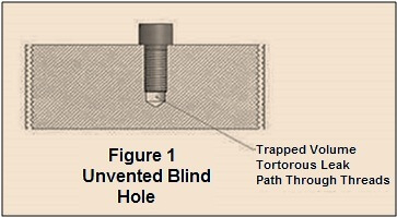
Also, many sources of virtual leaks arise from an original manufacturing procedure or a repair on a chamber or system. As an example, small volumes can be trapped that have a connection to the vacuum side and yet, given the conductance restriction, cannot be pumped out easily or quickly. Some common examples of virtual leaks caused by poor design follow.
Our first example, shown as Figure 1, illustrates how a small volume of air or gas can be trapped at the bottom of the threaded hole. This small volume will eventually slowly leak out through the threaded area when the furnace reaches a certain vacuum level and will continue to slowly affect the vacuum performance of the furnace.
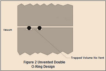
A second example of a possible virtual leak is shown in Figure 2. In this situation some trapped volume could occur if the O-ring groove is a dove tail design or if there are two O-rings and the space between them is not vented.
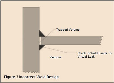
A third example of a virtual leak is related to improper or incorrect weld design. In this situation, a space could be left between members being butt welded. Should a small crack eventually appear in the weld area, leakage could occur and cause this undesired and difficult to find leak. This is illustrated in Figure 3.
It should be noted that most virtual leaks will not be detected in a normal leak checking cycle. The presence of a virtual leak will become apparent during the system pump down cycle when the ultimate pressures cannot be reached, i.e. hours, or it takes an excessive amount of time to reach blank off pressure.
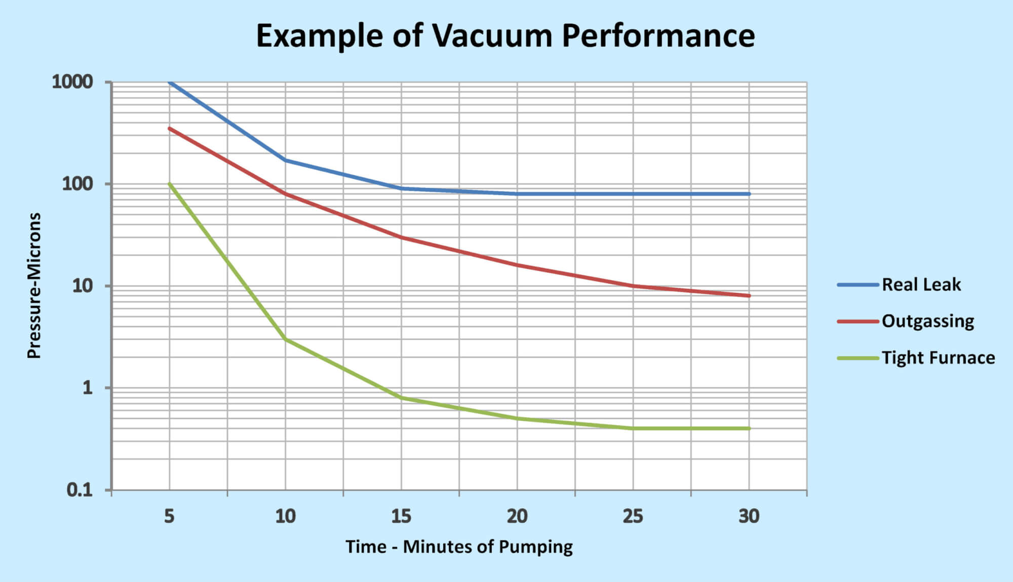
In most cases, physical leaks and outgassing are present simultaneously where the leak is a flat pressure and the outgassing is constantly reducing.
Figure 4 highlights three examples of what can result during pump down. As is illustrated, a real leak reaches a limit while an outgassing occurance continues to achieve better vacuum over time.
Determining a Vacuum Heat Treat Furnace Leak Rate
It is essential to know that a vacuum furnace is leak tight. Measuring how tightly the vacuum chamber is maintained is accomplished by performing a “Leak-Up-Rate” test.
There are various ways to prepare a furnace for a leak-up-rate test. Our recommendation on normal production furnaces is as follows:
Heat the empty chamber to approximately 100oF over the most recent highest process temperature for one (1) hour to thoroughly clean the furnace of product contaminants. Then nitrogen or argon gas cool the furnace to ambient temperature. Without opening the chamber, continually re-pump down the furnace to establish an ultimate vacuum level. This should continue for an extended period, usually, but no more than, two hours. After that time, the vacuum pumps are valved off and the system allowed to sit while the rise in vacuum level is measured. This leak rate is typically measured in microns/hour with certain standards established as acceptable for a given system. Normally a leak rate of 10 microns per hour is acceptable for most vacuum furnaces but may be lower or higher depending on the application or volume of the vacuum chamber.
A typical rate of rise curve could look similar to the one in Figure 5. If we break down this curve, we can conclude that the first 15 minutes represent a total of any real leak and outgassing occurring in the furnace. As things begin to stabilize, the rate of rise begins to straighten out slightly to represent the real leak that is occurring. If we analyze what occurred over the previous 30 minutes, we see a rise of approximately 6 microns, or extending this, 12 microns per hour. However, customarily we start from time zero, thus 10-20 microns per hour.
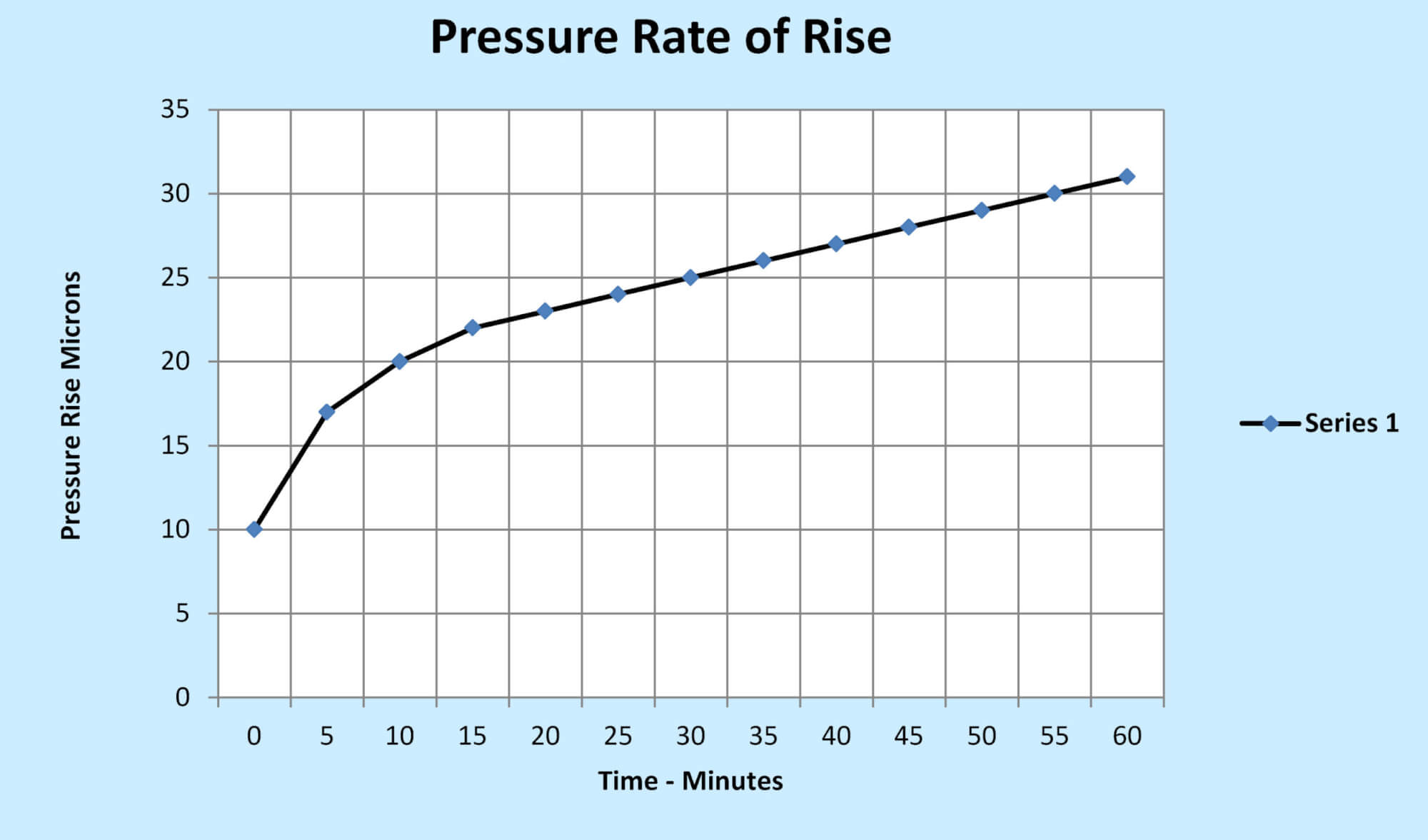
This would represent a marginally tight furnace with consideration given to possibly finding a potential leak, especially if critical product is being processed.
One should always remember that the results of observing a pump down cycle and then performing a leak-uptest are most often affected by the overall cleanliness of the furnace, and might not lead to an immediate detection of problems. Also, the rate of rise curve and other vacuum decay tests will not locate the leaks but will only indicate the relative magnitude of all leaks.
When pump down fails or an excessive leak rate is present, this suggests the need for a long high temperature bake-out on the hot zone emptied of work, fixtures, or work grids, to eliminate any suspected contaminants. However, this should be avoided as hot zone damage can occur in the bake-out if the true problem is a real leakage of air.
If the furnace fails the leak rate test, something is wrong regardless of prior leak testing methods. The leak simply has not been isolated or found.
Examples of Where Vacuum Furnace Leaks Might Occur
Based on the above and our experience, listed below are many examples of where leaks could occur.
- Furnace Door O-ring Seal
- High Vacuum Main Valve Seal
- Gas System Flanges
- Heat Exchanger Feedthroughs
- Nasty Water Leaks in the Heat Exchanger (i.e., water to vacuum)
- Internal Furnace Chamber Welds
- Pneumatic Cylinder Feedthroughs
- Power Feedthroughs
- Heating Element Power Feedthroughs
- Compression Seals as in thermocouple assemblies, wire feed-through glands, or thermocouple sheaths.
- Welds and Brazed Joints
- Shaft Seals on Vacuum Valves and particularly vacuum blower motors.
- Flexible Connectors in Piping
- Threaded Joints (Vacuum Plugs, Vacuum Gauge)
- Gasket Seals on Feedthroughs, Manifolds, Sight Ports, Cylinder Glands
- Other O-ring Seals
- Nasty Water Jacket to Vacuum Leaks
Safety Concerns in Leak Checking a Vacuum Heat Treating Furnace
Quench Gas Concerns
Often, leak checking requires an individual to enter the open vacuum furnace chamber during the checking process. This is especially true on larger furnaces such as car bottom furnaces. Maintenance and leak checking of any furnace chamber internals should only be attempted when the chamber has been completely purged of any residual gas remaining from a prior cycle. Residual quench gases still in the chamber even when the door is opened can cause asphyxiation and death.
The hazard is most critical if argon was used in the prior quenching cycle. Since argon is heavier than air, it can remain in low-lying areas such as a quench tank or service pit for many hours. It has no discernible odour and there is usually no advance warning before unconsciousness occurs.
Diffusion Pump Heaters
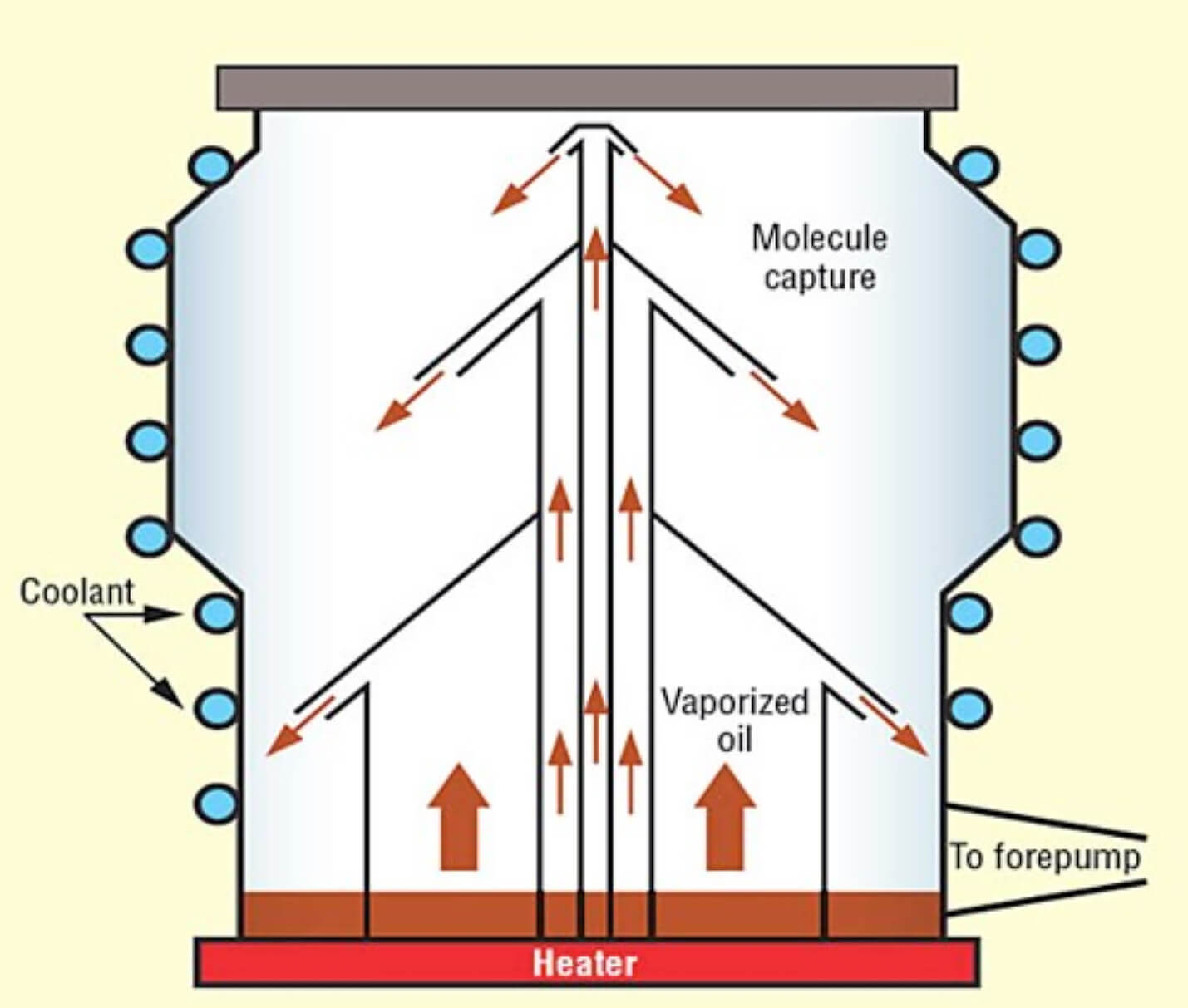
On furnaces equipped with oil diffusion pumps, maintenance and leak checking should only be attempted with care. As illustrated in Figure 6, the diffusion pump operates by boiling oil to form a vapor. Heated by electric heating elements at the bottom of the pump, the oil reaches a temperature of approximately 5000oF and higher, thus providing a very hot external surface until the pump has cooled. Any leak checking around this area of the furnace must be done with care. Never air release a hot diffusion pump to air, i.e. to check oil level, as it may explode and cause massive furnace damage.
Further Defining Leaks in Vacuum Heat Treat Furnaces
When a leak exists on a vacuum furnace system, the type of leak can be defined relative to the amount of flow occurring through the leak.
Turbulent Flow (Very rough vacuum)
Turbulent flow typically describes a gross leak situation. These leaks usually occur in unsoldered joints, open welds, open valves and plugs left off pipes. These types of leaks are usually the easiest to find.
Laminar Flow (Rough vacuum)
This term is commonly used to describe a small or fine leak. In this case, the leak is proportional to the differential pressure where doubling the pressure across the leak doubles the leak rate.
Molecular Flow (High vacuum)
This describes an extremely fine leak such as a virtual leak, or a membrane leak, as the result of a defective diaphragm in a valve or vacuum gauge. A leak like this occurs when the mean free path of the molecule is greater than the diameter or opening of the hole where the leak is escaping. In this situation, an increase in pressure has very little effect on the leak rate.
Also, gasses may penetrate through some solid materials such as elastomers (O-rings). These leaks are called permeation leaks. They are different from real leaks because the only way to prevent or stop them is to change to a less permeable material. These types of leaks usually occur in the 1×10⁻⁶ Torr range or higher vacuum.
Methods of Leak Checking Vacuum Heat Treat Furnaces
There are three commonly used methods of detecting vacuum furnace leaks: (1) via sound emanating from the leak; (2) vacuum decay highlighted on the vacuum gauges when using a solvent to penetrate the leak; and (3) the use of a Helium Leak Detector (mass spectrometer).
Noisy Leaks
When a vacuum furnace demonstrates difficulty pumping down to expected rough vacuum levels, it typically indicates a fairly large leak. This could be as a result of some changes or modifications that have recently been made to the furnace. As the furnace is struggling to pump down, walk around the furnace and listen for any hissing or high-pitched whistling, an indication that air is penetrating a seal. As this may be a very small sound, it is important that surrounding noises are eliminated.
Since most furnaces cool under positive gas pressure, closing the furnace and backfilling to maximum backfill pressure will allow you to check for pressure decay and any sound coming from exiting gas. This will often show areas where proper seals have been broken or need tightening.
Some operators or leak checking personnel will often use a stethoscope when checking for leaks, as its ability to transmit low-volume sounds and eliminate external noise is exceptional. Often in gross leaks or some smaller leaks, a standard paint brush and soapy wash solution is helpful. Brush the solution around suspected leak areas. Big leaks will blow big bubbles at the leak while smaller leaks will form very fine foam.
Vacuum Gauge/Solvent Detection
For many years, operators and leak checking personnel have been using solvents to assist in finding vacuum leaks. Most solvents used today are either acetone (preferred) or alcohol.
The vacuum gauge of the vacuum furnace instrument panel is a very sensitive instrument. In the solvent method, the operator sprays or brushes the solvent around the suspected leaking area and watches for movement in the vacuum gauge. If a leak exists, the entering acetone will affect the gauge reading level since the gauge is calibrated for air, not acetone. The operator should allow sufficient time for the acetone to affect the gauge, normally 20 seconds is sufficient.
The solvent procedure is more sensitive when the furnace is at lower pressures (below 1 Torr) and is most commonly used to find gross leaks. This also allows the furnace to reach a vacuum range where the technician can then employ a helium leak detector to uncover smaller leaks.
If a gross leak is found, it can be temporarily sealed to continue leak checking using a sealant such as “duck seal,” Glyptal® red alkyd lacquer, or Tek-Seal clear vacuum sealant. However, the leak checker must realize that this is a temporary fix and must be permanently repaired prior to running any gas quenching cycle at positive pressures.
Helium Leak detecting
The preferred method of leak detection is with the use of a Helium Mass Spectrometer Leak Detector, a highly accurate instrument for locating leaks, especially in hard-to-reach areas. A mass spectrometer can detect extremely small amounts of helium. Helium is the tracer gas of choice because it is inert, nontoxic, relatively inexpensive (in small quantities), and not easily absorbed. Helium also easily flows through small leaks and has only a trace presence in air (usually 5 ppm).
The Spectrometer is connected into the vacuum system; Helium gas is sprayed on any area where a leak is suspected. The leak detector will sense the presence of Helium passing through the leak. Helium leak detectors usually work best at levels from the system’s ultimate vacuum to approximately 10 Torr. In some instances, it is necessary to “bag” or isolate a specific area on the furnace and inject helium into the contained space. The Spectrometer is sensitive enough to locate leaks even in moving or transition (vacuum to pressure) seals.
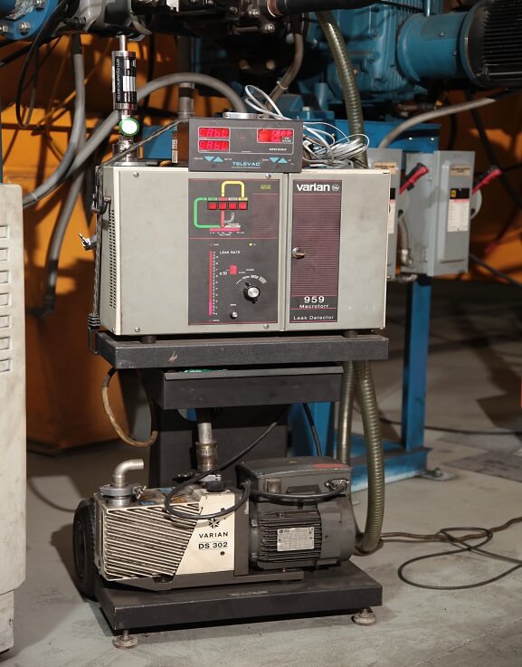
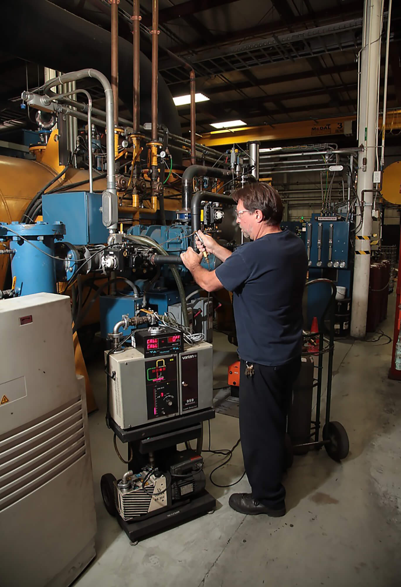
Figure 7 is the standard portable leak detector available through Varian Inc.
To connect a leak detector:
Connect the device between the blower and mechanical vacuum pump. You’re taking advantage of the high helium pumping speed of the high vacuum pump and blower, so response time is very good. Since the helium pumping speed for the mechanical pump is less than the blower, less helium is lost and sensitivity is good.
Typical Procedure For Leak Checking a Vacuum Furnace
A typical procedure for finding a leak in a vacuum furnace:
- Before starting any testing, make sure the helium leak detector is calibrated (checked with a calibrated leak) and working properly. Make sure there are no leaks within the leak detector itself by spraying a small amount of flow into the cabinet. In addition, leak check the connection point from the leak detector to the furnace.
- Connect the leak detector to the port on the roughing line with the ball valve closed.
- Make sure water is turned on to the diffusion and roughing pumps.
- Start the holding and roughing pumps.
- Manually open the foreline to check for leaks prior to turning on the diffusion pump. Be sure to close the foreline valve following this test.
- Slowly open the ball valve allowing the helium leak detector into the system.
- Leak check all welds, threaded fittings, and flanges on the foreline and roughing system by spraying helium sparingly into these areas.
- Repair any leaks resulting from this initial testing.
- If any leaks were found and repaired, repeat steps E through H and leak check again.
- If no more leaks are found, close the leak detector ball valve, and turn on the diffusion pump, allowing it to heat up for 45 minutes.
- Start the process cycle and let the furnace pump down to optimum level.
- If the furnace cannot cross over to high vacuum, open the ball valve slightly to the leak detector and leak check all flanges, threaded fittings, welds on the chamber, gas blower can, overhead piping, and vacuum switch copper lines. Fix any leaks found during this process.
- Now go over the entire system by spraying helium at a high rate of flow.
- If no more leaks are found, close the ball valve to the leak detector and remove it from the system.
- The furnace should now be fully checked and should be ready to return to production.
- If no external helium leaks are found and the furnace still has a high leak rate as revealed by the leak rate test, there are several other possibilities: Gas leaking into the furnace via the gas backfill valve or partial pressure valves, i.e. nitrogen or argon. Take these valves apart and look for dirt or defective seals or diaphragms.
- A possible water-to-vacuum leak from the gas cooling heat exchanger. Take the heat exchanger out of the furnace and look for water deposits at brazed joints. Pressurize the heat exchanger with approximately 100 PSIG air pressure and soap bubble all brazed joints. If necessary, submerge the heat exchanger in a tank of water and look for air bubbles. A heat exchanger that has been submerged in water must undergo an oven bake-out prior to being re-installed into the furnace system. Do this at 300oF for four (4) hours to boil out any residual water.
- When all else fails, consider that water may be leaking from the chamber water jacket to the vacuum internal. It could also be from some other water jacket-to-vacuum enclosure such as the gas blower or heat exchanger enclosure. Remove all components of the hot zone and inspect for possible water deposits that could result from water leaks. If there are no apparent deposits observed, air pressurize the jackets to approximately 30 PSIG and soap bubble all welds and joints. Sometimes leaks can occur as cracks or even corrosion in the center of the chamber tank. All chamber leaks must be weld repaired and tested, with no resulting bubbles present.
- Water leaking from a heat exchanger or vacuum chamber or other jacket into the vacuum will normally turn the roughing pump oil a milky color from a bad leak, or slightly discolored from a smaller leak. In a serious water leak, the vacuum chamber will not pump down below 1 Torr. If free water builds up in the bottom of the chamber or heat exchanger enclosure, over time the free water will freeze and form ice. Sometimes this will appear as frost on the air side of the chamber or heat exchanger tank.
Please remember that when using the helium leak detector, the time it takes for the leak detector to respond indicates the general area of a leak and further evaluation must be made to find the exact location. There is often the possibility of more than one leak within the same area.
If no leaks are found with the helium leak detector, this does not mean there are no leaks. Remember, the final test is the rate of rise test.
Conclusions on Vacuum Heat Treating Furnace Leaks and Detection Techniques
Leak detection is complicated and a detailed subject. All vacuum furnace users must eventually become experts in the “art” of leak checking or their operations will suffer difficult times.
All leak checking personnel should know and understand the following:
- The types of leaks that can occur, including the very difficult “virtual” leaks.
- How to properly perform a furnace leak rate check.
- Understand the safety aspects of leak checking.
- How to use the vacuum pumps and gauges while using a solvent solution to find simple leaks.
- Understand and have access to a helium leak detector for finding the more difficult vacuum leaks.
- How to properly repair or seal any vacuum leaks with consideration of both vacuum and positive pressure cooling cycles.
- Before starting a leak check, always review prior maintenance. Often a loose fitting like a replaced T/C improperly installed is the problem. Look for the obvious first before creating a more difficult situation.
Written By:
Real J. Fradette, Senior Technical Consultant, Solar Atmospheres Inc.
Contributor:

References:
- Varian, Inc, VS Series Leak Detectors for Vacuum Furnaces
- Daniel Herring, Finding and Fixing Vacuum Leaks, Industrial Heating, 2011
- Maintenance Procedures for A Vacuum Furnace, Jeff Pritchard, Steel Times International 2009
- Meyer Tool & Manufacturing, Vacuum Chamber Design: What is a Virtual Leak?
- Daniel Herring, Atmosphere Heat Treatment, Principles/Applications/Equipment, Volume 1 & Volume 2
- JM Lafferty, Foundations of Vacuum Science & Technology
- Basic Vacuum Practices, 3/E by Varian, Inc, reprinted by Solar Atmospheres
- Figures 1-3, https://www.mtm-inc.com/av-20100312-vacuum-chamber-design-what-is-a-virtual-leak.html
- Figure 6, https://slideplayer.com/slide/5876724/