A Review of Gas Quenching from the Perspective of the Heat Transfer Coefficient
High pressure gas quenching is a valuable tool to help the Heat Treater minimize part distortion, achieve both surface and core hardness, and optimize part microstructure. Understanding the role of the heat transfer coefficient–and that it can be measured–will help quantify the factors that influence quenching performance.
What is Pressure Quenching? The description most often used to define high pressure gas quenching is “accelerating the rate (speed) of quenching by densification and cooling of gas.”[1] One of the many reasons for the intense interest in this quenching technique is related to improved part distortion and higher core hardness. A critical concern in using this technology is to avoid sacrifice of metallurgical, mechanical or physical properties, that is retain the ability to transform a material to a microstructure that is similar, identical or superior to that of a known quenching medium (e.g. oil or salt). There is a wealth of published (and often confusing) empirical data on the subject and more being generated daily. To sift through this mass of information, an understanding of the basic principles of the technology is needed.
A Theoretical Understanding of the Heat Transfer Coefficient
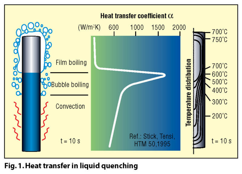
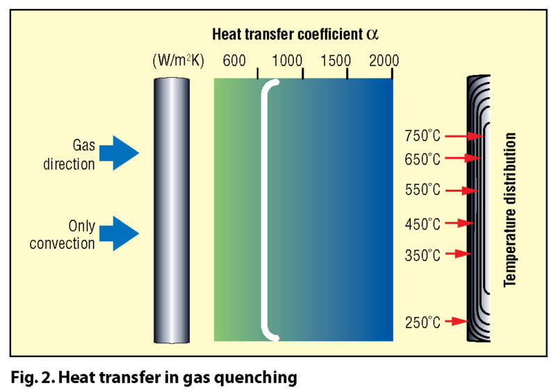
A key difference between quenching in a liquid and quenching in a gas lies in the different mechanisms involved in their heat transfer characteristics. Most liquids (Fig. 1) such as water or oil have distinct boiling points, and thus different heat transfer mechanisms (and rates) at various temperature stages (e.g. oil has three distinct heat transfer phases: vapor blanket or “film” boiling, nucleate or “bubble” boiling and convection). For gaseous media (Fig. 2) heat transfer takes place by convection only.
There is a relationship (Equation 1) that describes the convection heat transfer (q’) in terms of the heat flux (or heat flow) through the surface of a part that is proportional to the difference in temperature of the part surface (Ts) and the temperature of the quench gas (Tg) at any given moment in time.[2] This proportionality value is the heat transfer coefficient, α (“alpha”).
q’ = α (Ts – Tg) (1)
In convective heat transfer, a complex formula (Equation 2) describes the heat transfer coefficient (α) as dependent on the gas type (as described by its heat capacity (cp), its heat conductivity (λ), and dynamic viscosity (η) of the gas), and on a geometric factor (d), which represents the area of free passage of the gas for a specific load arrangement. The physical laws that illustrate how velocity (v) and pressure (ρ) influence the heat transfer coefficient are given by:
α = C v0.7 ρ0.7 d-0.3 η-0.39 cp 0.31 λ0.69 (2)
where C is a constant[3].
Thus the greatest influence on the gas-cooling rate is the magnitude of the convective heat transfer coefficient (α), which in gas quenching is dependent on velocity and pressure as well as gas temperature. In other words, for a given geometrical arrangement (e.g. transverse gas flow over a cylindrical body) and a given gas type (e.g. nitrogen or helium), the heat transfer coefficient is directly proportional to the product of gas velocity and pressure raised to an overall (system dependent fluid dynamics constant) power, which is generally between 0.5 to 0.8.[4]
A Practical Understanding of the Heat Transfer Coefficient
 Now that we have a theoretical understanding of the heat transfer coefficient, let’s understand its importance in respect to heat-treating applications.
Liquid quenchants such as water, polymer or oil have the characteristic that during their nucleate boiling phase, extremely high heat transfer coefficients can be achieved (Fig. 3). This is a distinct advantage in the temperature range where pearlitic transformation occurs and one not possessed by gas quenching. However, with the breakdown of the vapor phase at the onset of boiling, the so-called Leidenfrost phenomenon occurs and the result is a totally non-uniform heat transfer rate on different surfaces of the different parts and is dependent on a variety of variables and factors. This uneven transitory step creates huge temperature differentials and is the major factor in distortion when quenching in these media.
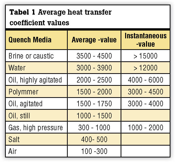
Although the maximum quenching “power” may be described by the instantaneous value of the heat transfer coefficient, the average heat transfer coefficient (Table I) provides a better relative comparison of the various quenching media since it represents the value of the heat transfer coefficient over the entire range of cooling (from the start to the end of quenching).
 Gas quenching avoids the Leidenfrost phenomena and therefore has an inherent capability to produce smaller temperature differences in a part during quenching, and thus less dimensional variation. However, as can be seen, its relative ability to successfully transform the microstructure of a part may be limited (Fig. 4).

Factors That Influence Quenching Performance
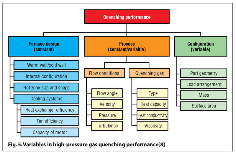
The calculation of the heat transfer coefficient helps us to determine how quickly a workload will cool. There are, however, other factors (Fig. 5) that significantly influence the cooling rate and overall time involved. These are generally classified as “external” factors and are sometimes included in the formula for the heat transfer coefficient (Equation 2), as the multiplier fa. The exponential value (a) for this factor is often equipment dependent and in the case of single chamber vacuum furnaces has been found to be in the range of 0.25 to 1.55.[7]
An understanding of the influence of these factors might be seen in a comparison of cooling rates between a single chamber vacuum furnace (hot chamber) and a cold (“blank body”) chamber (Fig. 6). However, this test is reported to be somewhat misleading [9] in that it involved the use of ISO-9950 test probe (a small test specimen, 12.5 mm diameter × 60 mm long was used, which was developed for laboratory testing of quench oils). In fact, the ISO-9950 standard is entitled: Industrial Quenching Oils—Determination of Cooling Characteristics—Nickel Alloy Probe Test Method, 1995-05-01. There are at least two main concerns why using this small specimen in HPGQ applications would be of concern:
- A small mass cools much quicker than a typical part and as such fails to represent the entire quenching process for most components.
- The small volume, having the thermocouple at its geometric center, fails to register a difference in cooling relevant to its position (vertical or horizontal) or to the gas flow direction (top to bottom, bottom to top, or alternating).
For these reasons, a significant research focus has been on probes designed to measure the heat transfer coefficient within the workload during the gas quenching. These are available from a number of manufacturers.
Advantages and Disadvantages of High Pressure Gas Quenching
Properly applied, gas quenching has several recognized advantages[2], which include:
- Safety
- Overall environmental impact
- Reduction of secondary manufacturing operations
- Optimization of dimensional variation
- Controllable cooling rates
- Overall economics
Of course, there are disadvantages[2], which must be factored into any consideration to use this technology. These include:
- Cooling rate limitations (i.e. quench severity)
- Reversed application of heat transfer rates (i.e. slow cooling rates in the pearlitic transformation range and high cooling rates in the martensitic transformation range)
- Regulations and (pressure vessel) codes
- High noise levels
Recent Developments
Work is being done to characterize steel hardenability by a number of researchers including those in Europe. In high-pressure gas quenching applications, the ability to change the quench behavior of gases by varying individual quench parameters (e.g. gas type and composition, pressure; circulation pattern and velocity) play an important role in achieving improved hardenability in high pressure quench applications. One example is research in the area of development of the gas quench equivalent of the Jominy test.[11]
Also, there are a number of probes and other devices designed to measure the heat transfer coefficient within the workload during the gas quenching.[12]. The measurement and recording of the quenching intensity (and heat extraction dynamics) in HPGQ applications has been solved by
using these types of probes. These types of sensors have thermocouples at precisely defined positions, enabling the calculation of the fl ow of thermal energy and thus the thermal heat transfer coefficient from the temperature measurement data during gas quenching (they are usually instrumented with three thermocouples—two of them near the surface of a cylindrical body, which enables the probe to distinguish different heat transfer characteristics in both the vertical and horizontal positions and one in the center. Thus, the influence of the “external” factors talked about above can be quantified. The measured quenching characteristics can be compared and data feed into a computer-based system for the prediction of hardenability, as well as determining the required quenching parameters (gas pressure, fan speed, gas type, water flow to the heat
exchanger, etc.) for a specific workload during the entire quenching process. This enables the quench intensity of the gas to be precisely determined.
Another new area is that of controlled heat extraction (CHE) technology. [13] This area explores the possibility of automatically following a predetermined heat extraction (temperature-time) cycle during high-pressure gas quenching. The influence of the heat extraction dynamics on hardness distribution after quenching is being actively studied.
- HPGQ process lasts much longer than quenching in liquid quenchants (assuming comparable dimensions and masses of the workpiece).
- Influential quenchant parameters (e.g. medium temperature, pressure and agitation rate) cannot be changed during the quenching process when using liquid quenchants, but they can be automatically changed during high-pressure gas quenching. This versatility offers new possibilities to influence the heat extraction dynamics during the quenching process itself. Furthermore, with the temporary addition of sprayed cryogenic liquid (e.g. nitrogen), an instantaneously drop in the cooling gas temperature occurs with a substantial increase in the quenching intensity. This can have a drastic influence on hardness distribution throughout the part cross-section as well as on residual stresses and distortion after quenching.
Summary: A Review of Gas Quenching from the Perspective of the Heat Transfer Coefficient
High-pressure gas quenching has the inherent capability of limiting dimensional variation within a part and within a workload. The key is understanding the factors that influence gas quenching and holding constant as many of these variables as possible to achieve a balance between
the speed of gas quenching and the uniformity (i.e. uniform heat extraction) of gas quenching. In this way, both repeatability (quality) and performance (productivity) will be achieved with an optimized microstructure.

High-pressure gas quenching technology has earned its rightful place as a valuable weapon in the arsenal of the heat treater. It should be applied in those applications where its advantages outweigh its disadvantages and, as with all technologies, the heat treater should have as complete an understanding as possible of the performance requirements of the product so as to evaluate the quench capability and application end-use.
Author: Daniel Herring, The Herring Group, Inc.
References:
- Herring, D. H., Pressure Quench, Furnace Design Extend Range of Applications, Heat Treating, September 1985.
- Edenhofer, B., Bless, F., and Bouwman, J.W., The Evolution of Gas Quenching in Today’s Heat Treating Industry, Conference Proceedings, 11th IFHT Congress on Heat Treatment, 19 – 21 October 1998, Florence, Italy.
- Preißer, F., The Physics of Gas Quenching, Conference Proceedings, Workshop on High Pressure Gas Quenching, ASM International, 1996, Indianapolis, IN.
- Herring, D. H., A Review of High Pressure Gas Quenching in Semi-Continuous Vacuum Furnaces, Proceedings, ASM Heat Treat Conference 1997.
- Hick, A. J., The Wolfson Test for Assessing the Cooling Characteristics of Quenching Media, Heat Treatment of Metals, 1983.3, page 69.
- Compilation from numerous literature sources by various authors writing on the subject of high pressure gas quenching.
- Carter, George C., Optimizing Gas Quenching, Advanced Materials & Processes, 2/96.
- Wingens, Thomas, Ipsen International, private correspondence.
- Private Correspondence, Professor Bozidar Liscic, Faculty for Mechanical Engineering Croatia.
- Segerberg, S. and Troell, E., High-pressure Gas Quenching using a Cold Chamber to Increase Cooling Capacity, Heat Treatment of Metals, 1997, p.21-24
- Lohrmann, M., Hoffmann, F., and Mayr, P., Characterization of the Quenching Behavior of Gases, Conference Proceedings, Heat Treating Equipment and Processes, ASM International 1994, Schaumburg, IL.
- Herring, D. H., Applying Intelligent Sensor Technology to Problems Related to Distortion, SME Conference Proceedings, Quenching and Distortion Control, 1998.
- Liscic, B., Critical Heat-Flux Densities, Quenching Intensity and Heat Extraction Dynamics During Quenching in Vaporizable Liquids, Conference Proceedings, 2003 Heat Treat Conference & Exposition, ASM International, Indianapolis, IN.