Ask the Expert: Solar Atmospheres of Western PA’s Director of Sales Outlines a Path for a Successful Heat Treatment on Your Additive Manufactured Parts
 1. My parts have been laser printed. Is cleanliness still a concern?
 1. My parts have been laser printed. Is cleanliness still a concern?
Generally, laser printed parts are free of oils and coolants that haunt traditional manufacturing practices. However, we have seen build plates with contamination (especially large ones with lifting holes) that have been resurfaced via conventional machining. Often these post-AM geometries hold residual oils and debris. These materials, if not removed, can discolor, and contaminate your build. Also, you should consider extraneous powder inside the build itself. You would be surprised at how much powder comes out of a complex build by just blowing it off with 80 PSI of air. While these powder particles may not affect the integrity of the build, they may end up deposited on your furnace shielding and heating elements. Expect to replace parts should this happen to your furnace.
2. To keep my build bright and clean, what vacuum levels should be achieved when stress relieving, annealing or aging?
Great question, but don’t stop there! Many of the new additive AMS specifications are providing guidance on vacuum levels that should be maintained (i.e., 1×10⁻⁴ Torr or lower or less than 5×10⁻⁵ Torr) during processing. These vacuum levels, in a clean, baked out furnace with clean fixturing, should be relatively easy to achieve and maintain. The bigger question is, do you know how to perform a proper leak rate in your furnace? Limiting leak rates to 5 or 10 microns/Hg per hour is very important when processing many titanium alloys, PH grades and all Zirconium / Niobium alloys.
3. How do I ensure proper temperature on my AM part?
We all know that we should use calibrated / surveyed furnaces along with contact work thermocouples (Work T/C’s). If the Work T/C’s cannot be placed into the part, they should be placed into a representative cross-sectional thickness block of the same alloy. However, in many cases the placement of Work T/C’s in AM parts is different. Consider .250” thick printed parts on a 12” sq. build plate that is 3” or 4” thick. Just placing a Work T/C into the thickest section of your build plate will not work. These build plates act as a heat sinks and will prevent the printed parts from reaching the required temperature for the full amount of time specified. In addition, nothing is worse than pulling your AM parts out of the furnace only to watch it all turn blue right before your eyes because the build plate is still over 500°F! Consider placing a Work T/C in the thickest portion of the build block for reference, you may be surprised what you see.
4. My furnace is clean, parts are clean, what else should be considered?
I hate to say it, but it doesn’t stop there. Not only should you know the purity and dew point of your process gasses (nitrogen, argon, helium and hydrogen), but oxygen levels should also be checked. The furnace can be tight, clean, and hold a deep vacuum for the duration of the run but then be ruined by cooling the load with contaminated process gas. Solar has written extensively on process gas purity and how to properly monitor gas quality. Reach out to us to discuss in more detail. You should be able trust your gas certification. But it’s never a bad idea to verify.
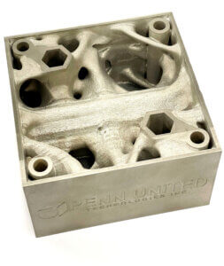
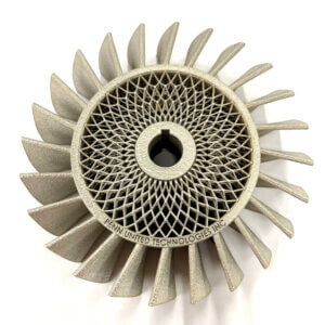
5. My build contains many different cross-sectional thicknesses / geometries. How can I minimize distortion?
No doubt that AM is exploring geometries that could never be achieved by traditional machining. Some of these builds will never uniformly heat or cool and that can contribute to distortion. Solar has a good video outlining steps to minimize distortion by stress relieving. The video specifically discusses heating ramp rates, cooling rates and thermocouple differentials. We recommend you start there and see if those variables can fix the problem. Recently we had an extremely complex build with an indescribable configuration. Even with a picture you couldn’t fully appreciate the configuration complexity. Let’s just say it went from 1” thick from the build plate to .090” thick then back to 1” thick. Plus, along the build height, there were holes, vents, pockets, large voids, etc. It was scrap waiting to happen! We convinced the customer to print a 3D clam shell (two halves) to place around the part to assist in uniform heating and cooling. Sometimes complex geometries require prior dialog and a willingness to take reasonable risks.
For more information: https://solaratm.com/markets/additive-manufacturing
And featured in Aerospace Manufacturing & Design Magazine: https://www.aerospacemanufacturinganddesign.com/article/questions-with-michael-johnson-october-2022/